“Datamodelling is the act of making an abstract representation of a set of concepts, properties, relations, and constraints on data entities”
Making a visual representation of how your data is structures is a good practice because you can work out the kinks and unexpected discoveries before implementing it in your code.
An Entity-Relationship Diagram, or ERD, is a datamodel that shows how different entities(tables, essentially) interact with one another. The diagram is not dependent on any database (so it does not have any tables or keys).
Unlike class diagrams, use case diagrams and activity diagrams, ERD’s are not part of the UML language. ERD’s are its own type of diagram, while UML is a type of making diagrams.
Parts of an ERD
An ERD essentially consists of 3 parts.
- The entity
- Attributes(properties)
- relations
The entity contains attributes and is connected to other entities trough relations.
Entities
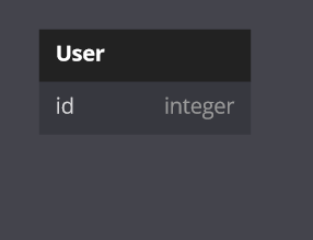
Entities are the objects that make up tables. Their name in either PascalCase or all CAPS. Entities are a collection of Attributes
Example
Attributes
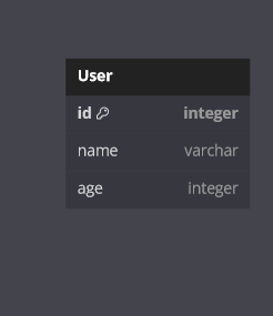
Attributes add information to entities. It’s essentially the columns of the table.
Attributes go underneath the divider line and are written with their datatype next to it.
If an attribute is the unique identifier (primary key), it will get a star next to its name (or some other identifier). Only one unique identifier exists per entity
Example
Relations
Relations are the connections between entities and how one interacts with the other. Relations are depicted by a line with different kinds of arrows.
Binary relations
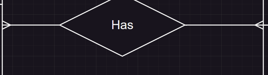
A binary relation is a relation between two entities. It’s the simples and most common relation of the, all. In between the two entities, there’s usually a diamond with a fitting name for the relation.
Example
dbdiagram didn’t support relation diamonds so were back to drawio babyy
Relation cardinality (size)
A relation can have different sizes, and i don’t mean the number of entities in a relation. I mean how many of one entity can another entity contain. Let me give an example.
Let’s say you have an entity called jukebox. A jukebox can have different colors, sizes, materials, etc.. but most importantly, a jukebox contains multiple songs. Now in an ERD that would look something like this: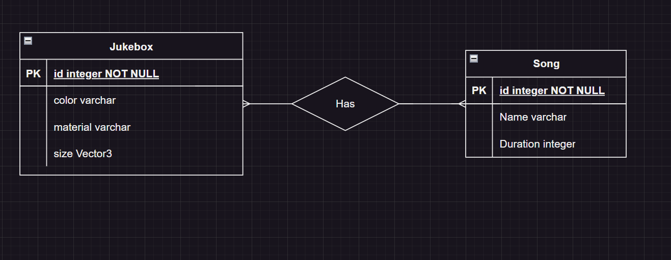 If you look at the relation, you can see theres a tiny split
This means that a jukebox can contain multiple songs, but of course a song is not contained to a single jukebox, so a song can have multiple jukeboxes too. This type of relation is called a many-to-many relation. There are 3 types of relations within an ERD
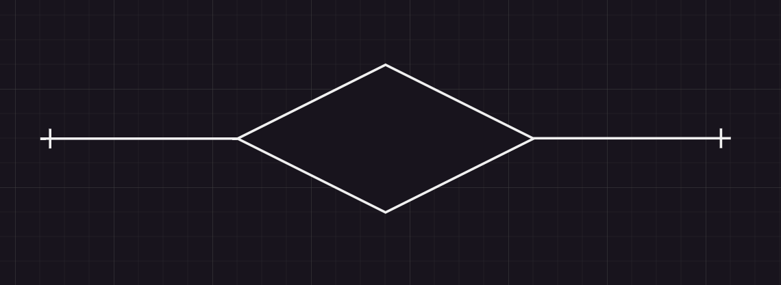
One-to-one
A one to one relation is the simplest of them all. It means that one entity contains one (other) entity. A one is depicted by a line trough the relation line at a 90 degree angle. One person has one mobile phone and one mobile phone has one person
Example
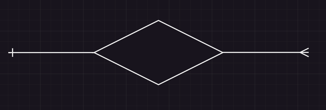
One-to-many (many-to-one)
A one to many relation means that one entity contains multiple entities (or multiple entities contain one). Many entities are depicted by three splitting lines. One person goes to one school, but multiple people can go to the same school.
Example
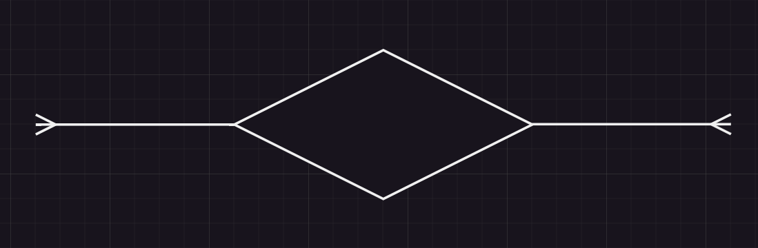
Many-to-many
The many-to-many relation has been explained above. It means that multiple entities can have more than one entity. One person can have multiple names and those names can be used by multiple people.
Example
Relation optionality
Relation optionality is just like cardinality an addition to a relation.
The optionality of a relation is the minimum number of entities that exist within an entity.
Optional (circle)
A circle means that an entity may contain another entity.
Example
The left contains either zero or one entity, the right contains zero or many entities.
Required (strike)
A strike means that en entity has to contain another entity.
Example
The left means exactly one entity, the right means one entity at minimum Keep in mind that the one relation now has two strikes
Intersection entities
Intersection entities are used at many-to-many relations, because you can’t really store a list of the entities in either, so you’ll use an in-between entity to store both lists.
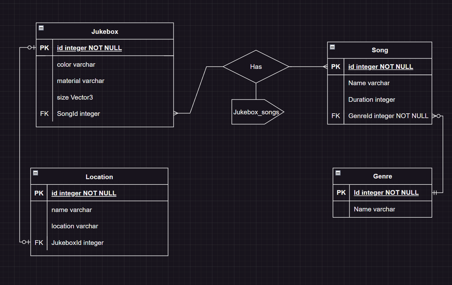
Everything combined
If we combine everything mentioned in this article on top of the jukebox example, we can get something like this: