Resistors
A resistor is one of the most common electrical components out there.
They generally look like this: 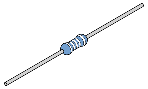
Law of Ohm
Resistors have these colored rings on them to depict their resistance(Ohm, or Ω).
The way to calculate the resistance using voltage and current is: Where U is the voltage and I is the current.
Important
If the resistance of a resistor increases, its voltage also increases
Here’s a helpful diagram to estimate their resistance: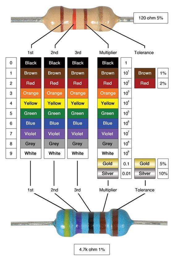
Symbol in a diagram
A resistor is drawn as a rectangle in diagrams. Their value is depicted by the unit Ohm or an omega symbol: Ω
Diode
A diode only allows the flow of power from one side, but not the other.
Symbol in a diagram
A diode is depicted by a triangle with a stripe on the tip: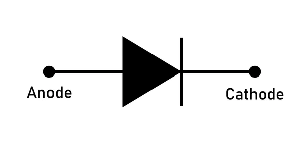
The flow comes in on the positive side (the anode) and flows out of the negative side (the cathode)
Light Emitting Diode (LED)
An LED is a diode that emits light (shocker). Because a led is an anode, it only works one way. Knowing which end is the anode and cathode is very simple: the long end is the anode, and short end the cathode.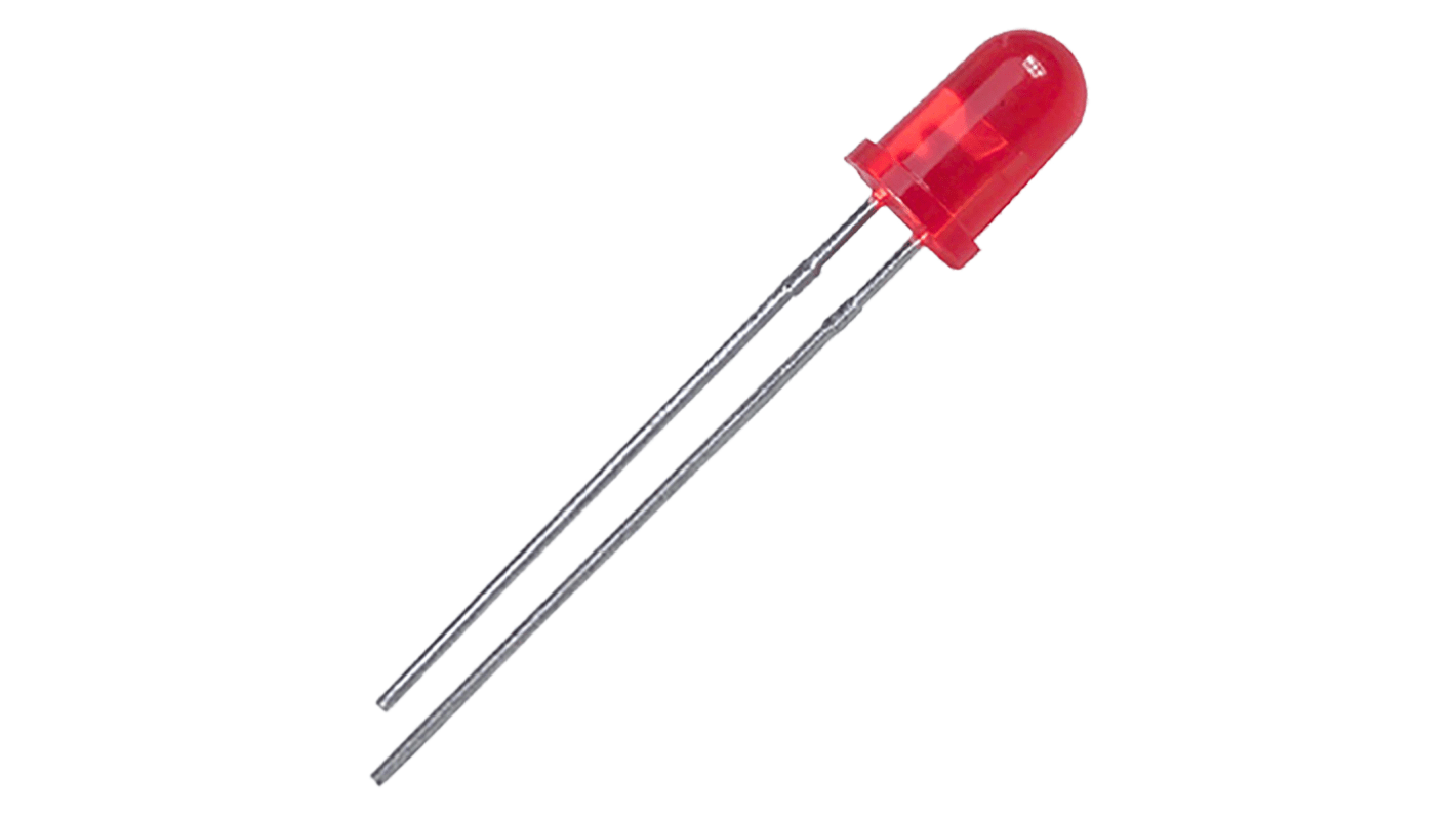
Threshold power and resistance
With resistors, when their voltage increases, so does their current. With LED’s it’s a bit different. If the voltage is lower than the threshold voltage, there wont be any light coming from the LED because it is not active.
But as soon as the threshold is met, the current will quickly increase which can damage the LED. To limit the current that can pas trough the LED, we place a resistor in between.
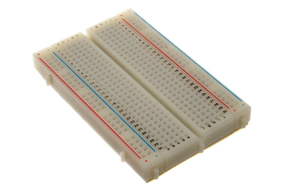
Breadboard and power
A breadboard is a plastic component with metallic rows which have a bunch of tiny holes. Breadboards make you able to connect electrical components without the need to solder anything. They look like this:
The two outside columns are connected vertically, and every middle column is connected horizontally: 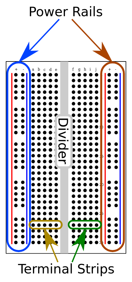 The power feed is plugged into the positive and negative strip (+ and -), and the components are placed in the terminal strips.
Colored cables
To prevent confusion and accidental misconnecting, all electrical cables are color coded. Some colors are reserved for specific functions, like:
- Red: Positive power (goes out of the positive end of the power supply)
- Black: Ground cable (goes into the negative end of the power supply)
Other colors can be used to differentiate certain circuits within the system.